
There is a small black flip-lid box on the strut tower in your MX-5's engine bay. Mazda calls it the Data Link Connector, the DLC. It is the single most useful thing in the bay if you know what is inside it: bridge the right two terminals and you can set the base ignition timing, prime the fuel pump, run the radiator fan, and read the fault codes without a scan tool. The catch is that the lid sticker that tells you which pin is which is almost always missing or faded. This is the map.
It is also the companion to our ignition timing note. That job starts here, at the terminal marked TEN.
Read it from the terminal side
Every map below is drawn the way the factory drew it, looking into the open box from the terminal side, with the loom entering from the left and the 12V feed (+B) in the top right corner. Before you trust any single position, find a known terminal first. +B is the only 12V feed, so probe for that, or find GND, and use it to confirm left from right. Wire colours and exact positions vary by year and market, so the rule on every one of these is the same: confirm against your actual car before you rely on it.
The terminal maps
Mk1 · NA 1.6
1989 to 1993
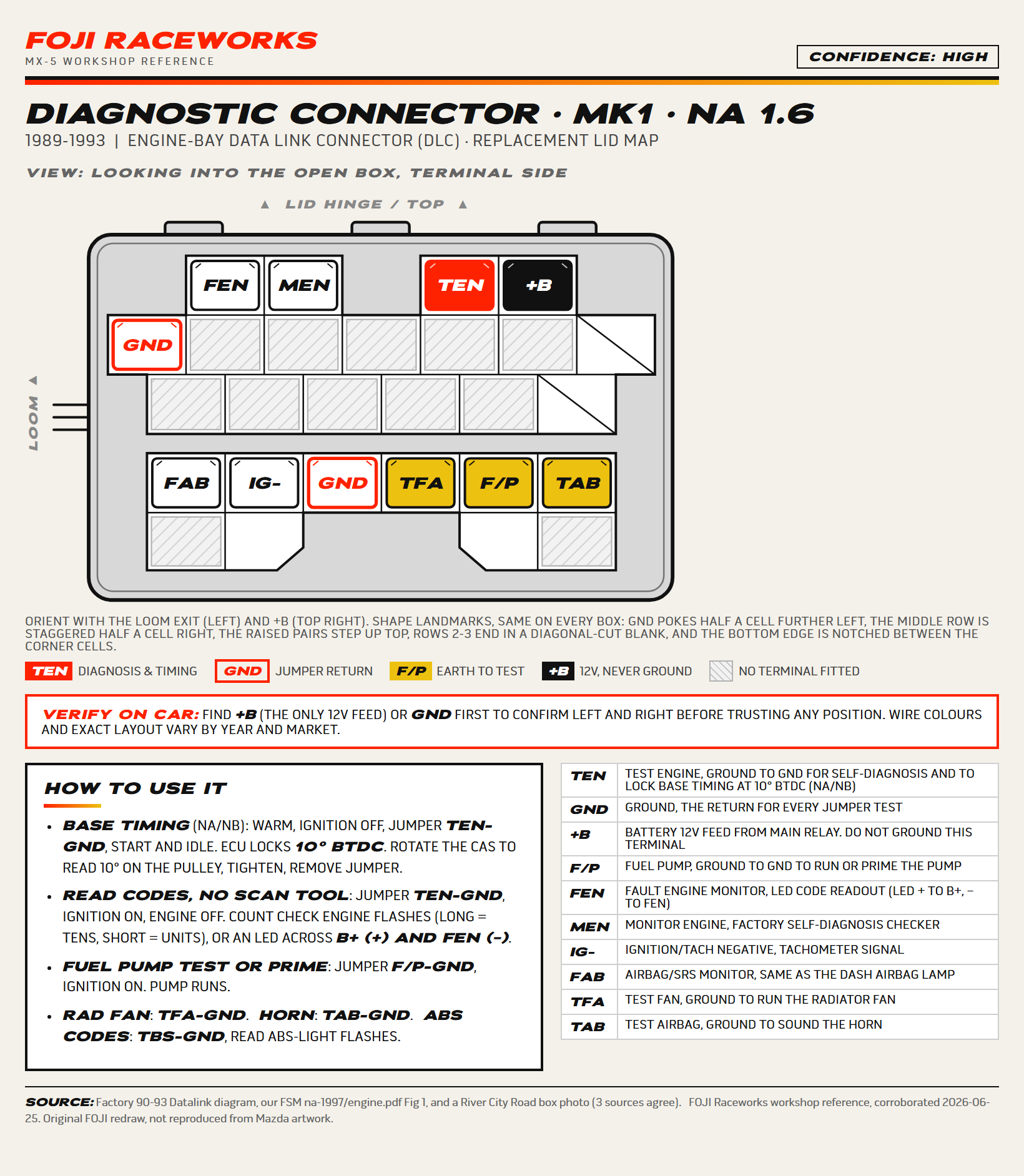
Corroborated by the factory 90 to 93 Datalink diagram, our FSM (na-1997 engine.pdf Fig 1) and a real annotated NA box photo. Three sources agree.
Download this sheet (PDF, A4)Mk1 · NA 1.6 & 1.8
1994 to 1997
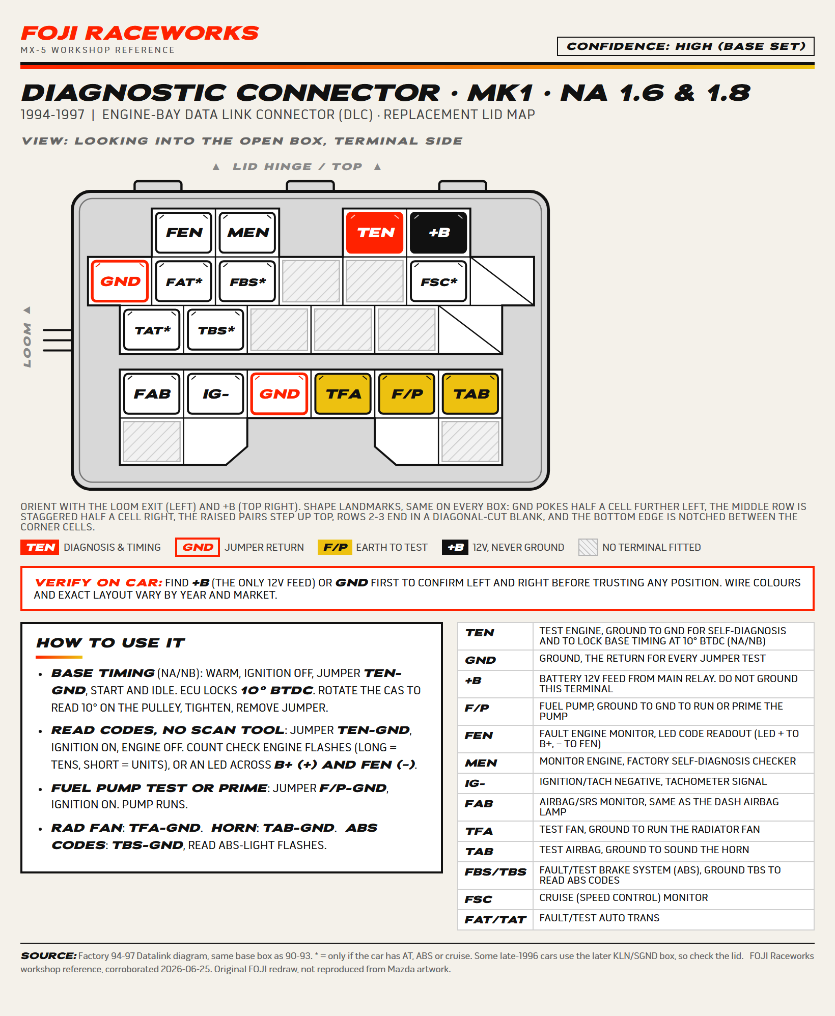
Same base box as 90 to 93. Terminals marked * are only present if the car has auto trans, ABS or cruise. Some late 1996 cars were built with the later NB-style box, so check the lid.
Download this sheet (PDF, A4)Mk2 · NB
1999 to 2000
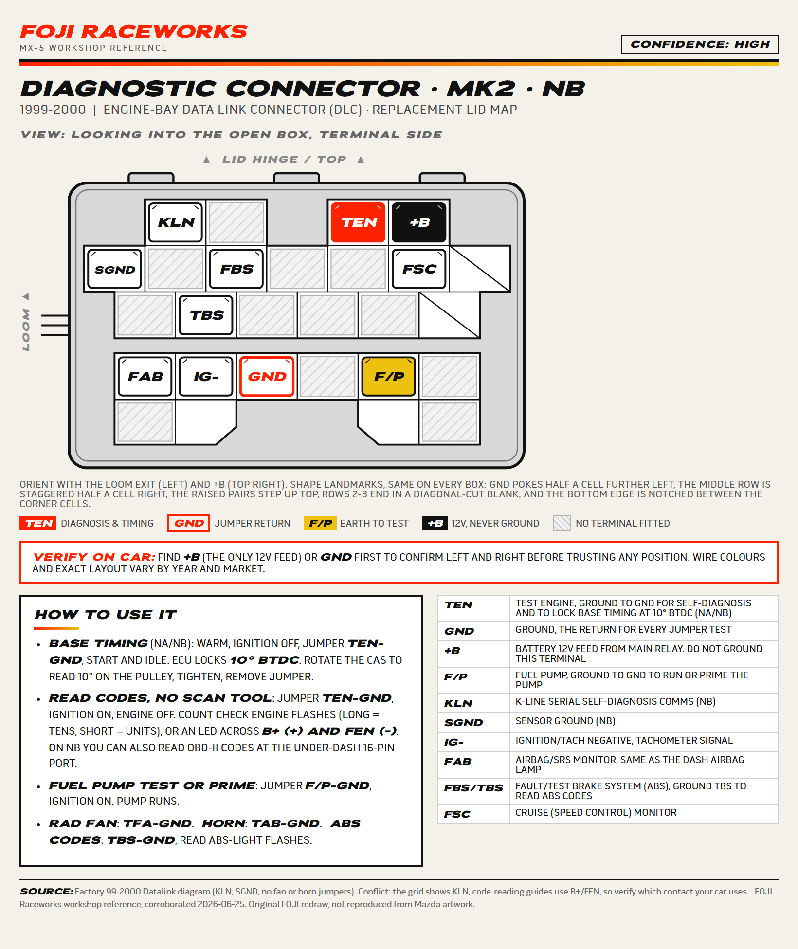
Factory 99 to 2000 Datalink diagram (KLN and SGND replace FEN and MEN, the fan and horn jumpers are gone). Conflict: the grid shows KLN, but some code-reading guides read from B+ and FEN, so confirm which contact your car uses.
Download this sheet (PDF, A4)Mk2.5 · NB2
2001 to 2005
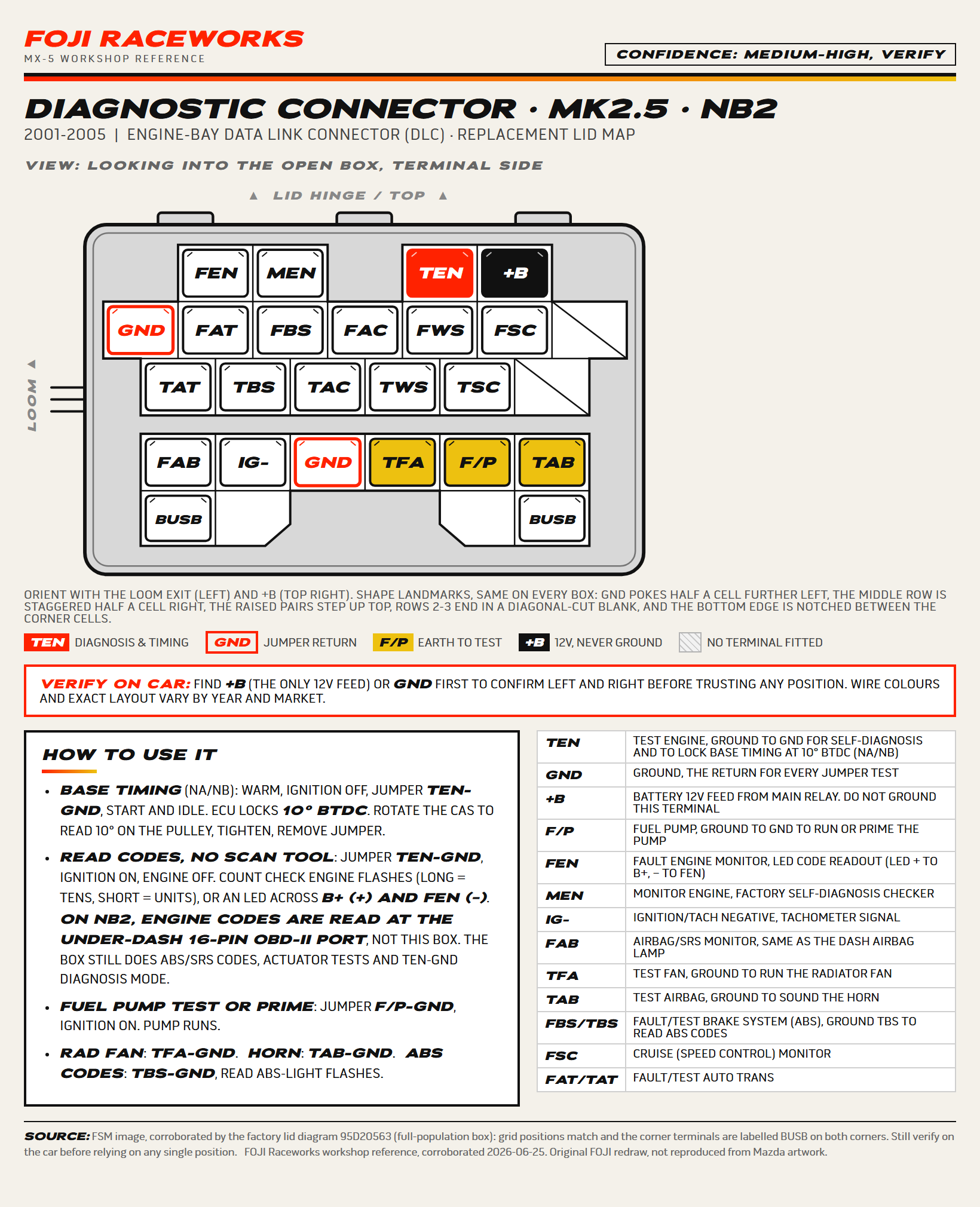
From a single factory image. The corner BUS terminals and the F/T expansion labels are not individually verified. Treat the less common pins as a starting point and confirm on the car.
Download this sheet (PDF, A4)A note on the Mk2.5: on that car the engine fault codes are read at the under-dash 16-pin OBD-II port, not at this box. The box still earns its place for the ABS and SRS codes, the actuator tests, and TEN to GND diagnosis mode.
For the workshop wall
Each generation above has its own PDF download. If you would rather have the lot on one document, this is all four maps as one PDF, one generation per A4 page, with the legend and the verify-on-car note built in.
Download the full set (PDF, all four)What each terminal is
| Terminal | What it is |
|---|---|
| TEN | Test ENgine. Earth to GND to enter self-diagnosis and lock base timing at 10 degrees before top dead centre (NA and NB). |
| GND | Ground. The return for every jumper test. |
| +B / B+ | Battery 12V feed from the main relay. Never earth this terminal. |
| F/P | Fuel Pump. Earth to GND to run or prime the pump. |
| FEN | Fault ENgine monitor. LED code readout (LED positive to B+, negative to FEN). |
| MEN | Monitor ENgine. Factory self-diagnosis checker. |
| KLN | K-Line. Serial self-diagnosis comms on the NB. |
| SGND | Sensor ground on the NB. |
| IG- | Ignition and tacho negative. Tachometer signal from the coils. |
| FAB | Airbag and SRS monitor. Same signal as the dash airbag lamp. |
| TFA | Test FAn. Earth to GND to run the radiator fan. |
| TAB | Test Airbag. Earth to GND to sound the horn. |
| FBS / TBS | Fault and Test Brake System (ABS). Earth TBS to read ABS-light codes. |
| FSC | Cruise (speed control) monitor. |
| FAT / TAT | Fault and Test Auto Trans. |
What you can do with it
All of these are done with a single short jumper wire between two terminals. Earth means bridge that terminal to GND.
- Set base timing (NA and NB): warm the engine, ignition off, bridge TEN to GND, then start and idle. The ECU locks ignition to 10 degrees before top dead centre so you can read it on the pulley with a timing light. The full walk-through is in the ignition timing note.
- Read fault codes without a scan tool (NA and NB): bridge TEN to GND, ignition on, engine off. Count the CHECK ENGINE flashes, long flashes are tens and short flashes are units, or read an LED across B+ (positive) and FEN (negative). On the Mk2.5, use the under-dash OBD-II port instead.
- Prime or test the fuel pump: bridge F/P to GND, ignition on, and the pump runs.
- Run the radiator fan: bridge TFA to GND. Sound the horn: bridge TAB to GND. Read ABS codes: bridge TBS to GND and count the ABS-light flashes.
Before you trust a pin
- Find +B (the only 12V feed, top right) or GND first, and use it to confirm left from right before counting across.
- Never earth +B. It is a live 12V feed and grounding it is how you cook a relay or worse.
- Layouts vary by year and market, including a running change on some late 1996 cars. The maps above are corroborated against at least two sources each, but they are a guide, not a guarantee for your exact car.
- The Mk2.5 map is built from a single factory image, so treat the less common terminals as a starting point and verify them on the car.