
When you wire in a standalone, chase a no-start, or adapt a loom onto a different car, the first thing you need is the factory ECU pinout: which cavity is which pin, what each pin does, and what colour the wire is. Mazda made this awkward. The plug face is barely documented for some generations, and the colours move around between year builds and markets. So we drew our own, from our own parts.
Below are the factory ECU connectors for the MX-5 from the 1.6 Mk1 to the 1.8 VVT Mk2.5. Each sheet is a FOJI original, drawn to the real connector face from donor plugs and ECUs on the bench, with every pin, its function, and its wire colour, and the pins colour-coded by what they do. The engine-bay diagnostic box is a separate connector, covered in its own note.
Read this first
Wire colours change between year builds and between markets, and most of the colour tables here come from the factory US wiring diagrams. Treat the colour as a starting point, never as gospel. The cavity map and the function are the reference. Before you cut, crimp, or trust any single pin, ring it out and confirm it on your actual car. Every sheet carries that same note for a reason.
How to read the sheets
Every plug is drawn as the front of the harness plug, the mating face, held with the latch up, which is what you see when the plug is in your hand. Pin A is ringed in red as the anchor. Find a known pin first, usually the 12V feed or a ground, and use it to confirm left from right before you count across. The wire side, looking into the ECU header, reads as a mirror of what is drawn. Each cavity is tinted by what the pin does:
The connectors, by generation
Tap any sheet to open it full size. Each generation also has its own PDF to print for the bench.
Mk1 · NA 1.6
1989 to 1993
B6ZE, OBD-I, optical cam angle sensor, no immobiliser. Two connectors.
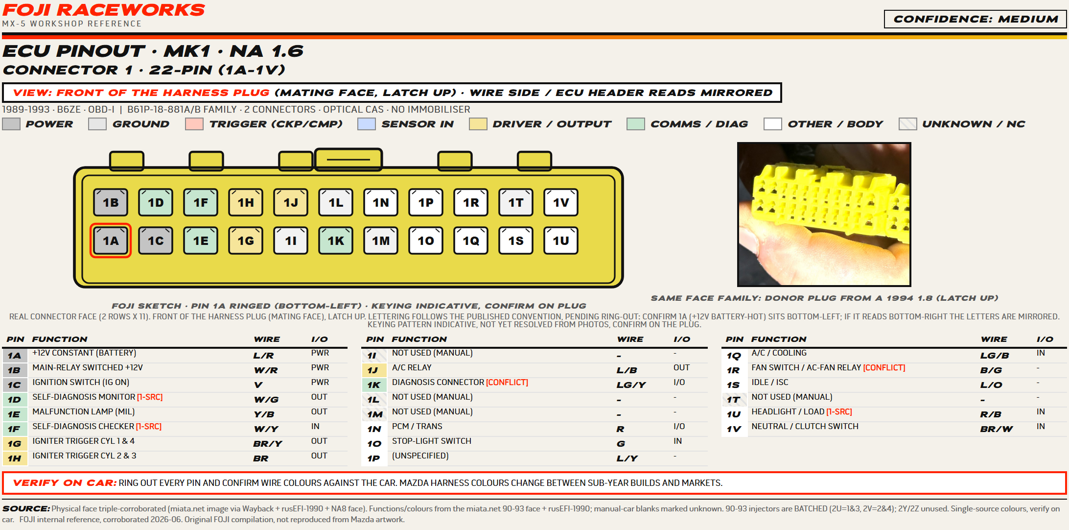
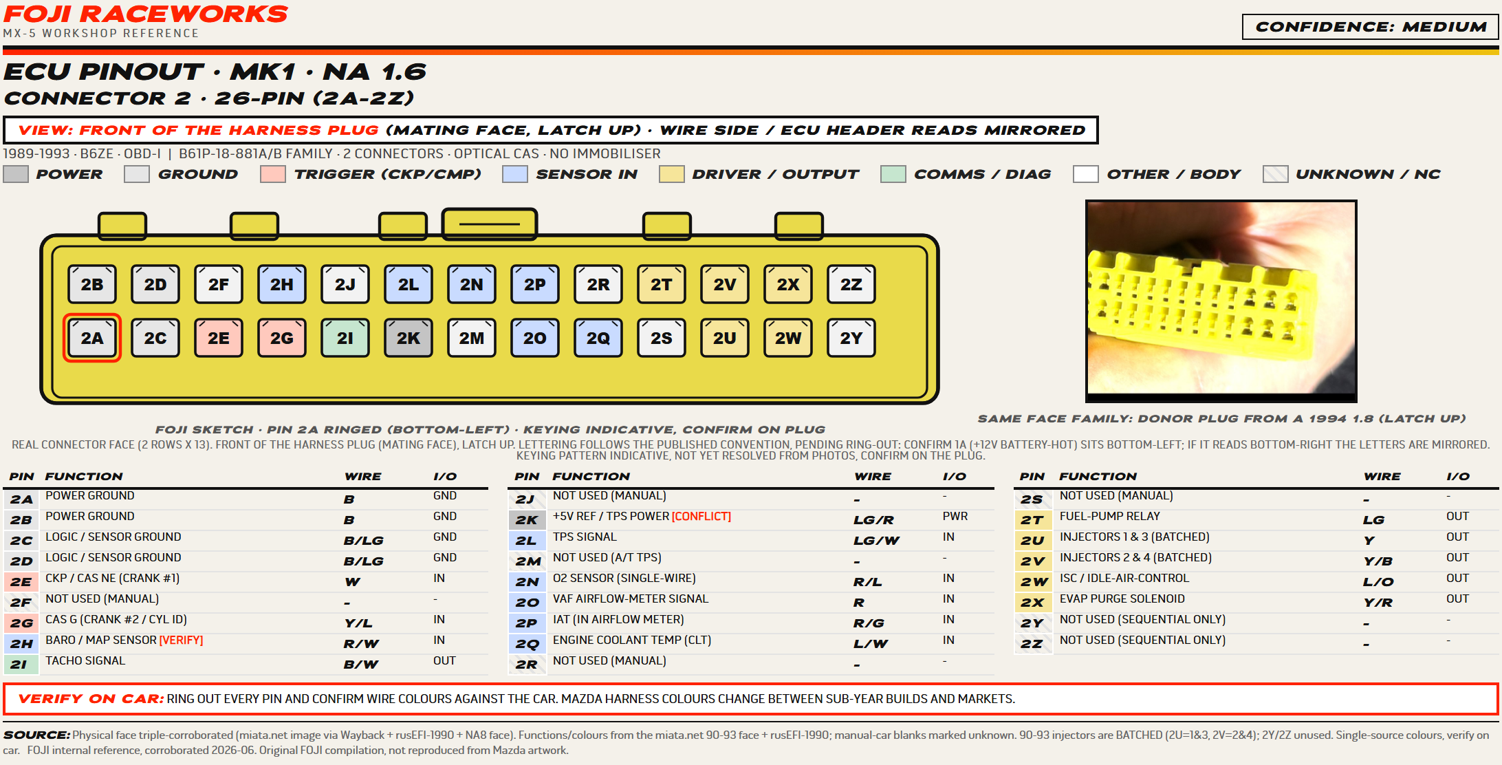
The early 1.6 ECU. On this car the injectors fire batched (2U is cylinders 1 and 3, 2V is 2 and 4) and the mid-connector pins depend on trim, so the manual-car positions marked unused can carry a wire on an auto or a loaded car. Colours are mostly single-source, so treat them as a starting point.
Download this sheet (PDF, A4)Mk1 · NA 1.6 & 1.8
1994 to 1995
B6 and BP, OBD-I, magnetic cam angle sensor. Two connectors.
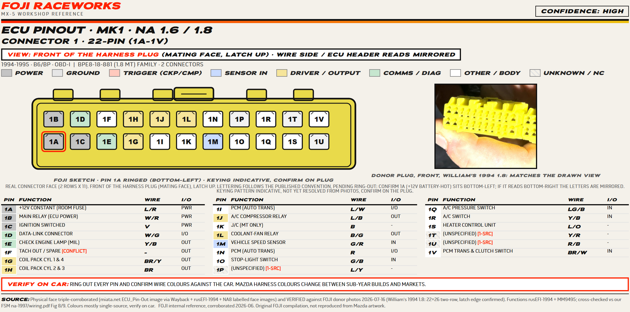
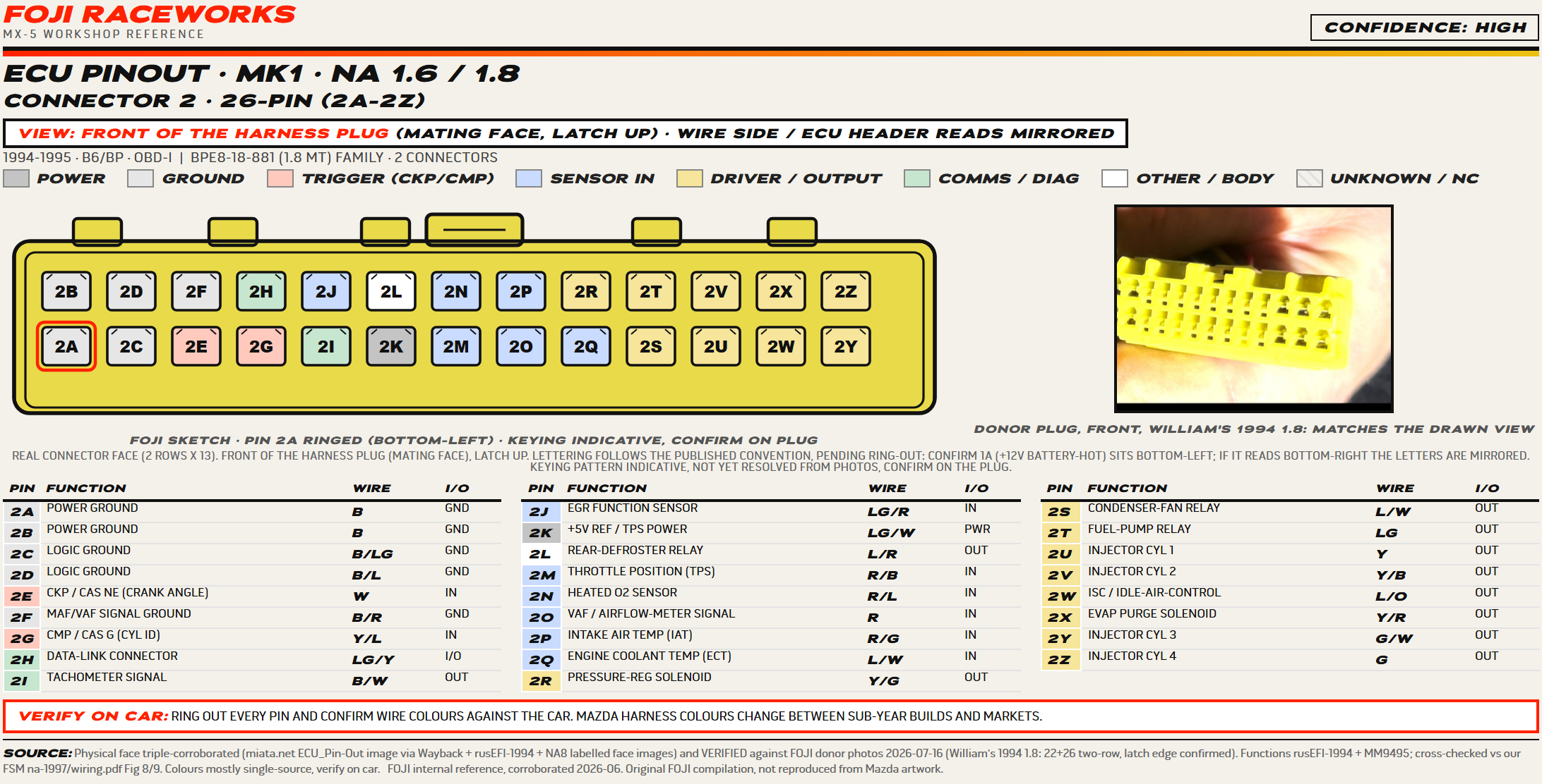
The face on both plugs is verified against a real donor plug from William’s 1994 1.8, so the cavity map and the latch edge are solid. Injection is sequential here, one driver per cylinder, unlike the batched early 1.6. Colours are mostly single-source, so confirm them on the car.
Download this sheet (PDF, A4)Mk2 · NB1
1999 to 2000
BP non-VVT, OBD-II, return fuel, generally no immobiliser. Three connectors, 64 positions.
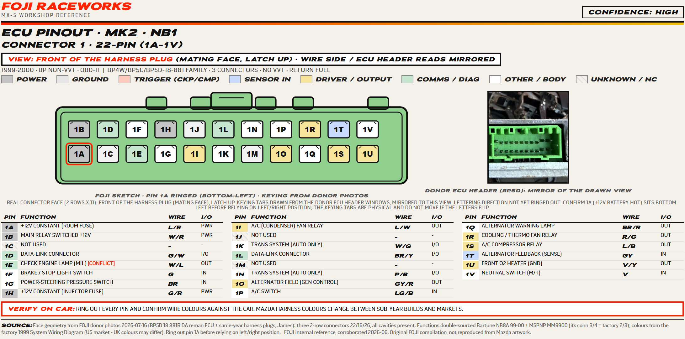
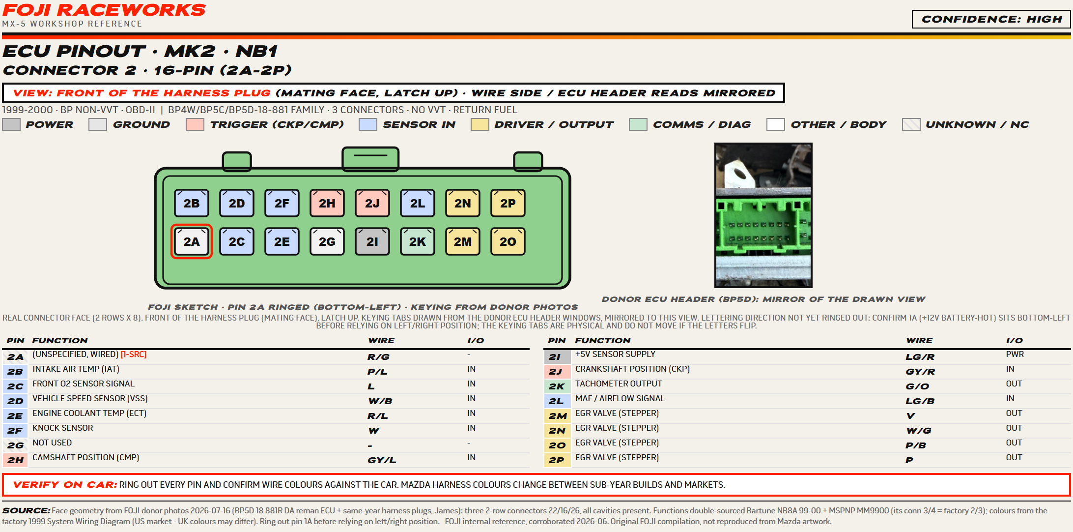
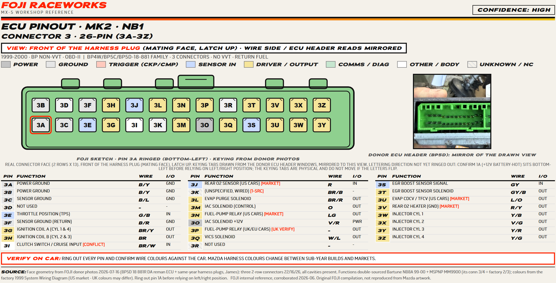
Drawn for the first time from our own donor parts, a BP5D reman ECU and same-year harness plugs from the scrapyard, because Mazda only ever published this one as a schematic, never as a plug face. Functions are double-sourced. Colours come from the factory 1999 US wiring diagram.
Still to confirm on car
- The lettering direction is not yet ringed out. Pin 1A is the battery-hot 12V feed, and it should sit at the bottom-left as drawn. If it rings out at the bottom-right, the letters are mirrored left to right. The keying tabs are physical and do not move if that happens.
- The fuel-pump relay is on pin 3N on the US diagram. UK and EU cars are expected to use 3P instead, and we have not yet captured the UK wire colour for it.
- Pins 2A and 3K are wired on the factory diagram but no source names what they do.
Mk2.5 · NB2
2001 to 2005
BP-VVT, OBD-II, returnless fuel, immobiliser on pin 3S. Three connectors, 72 pins.
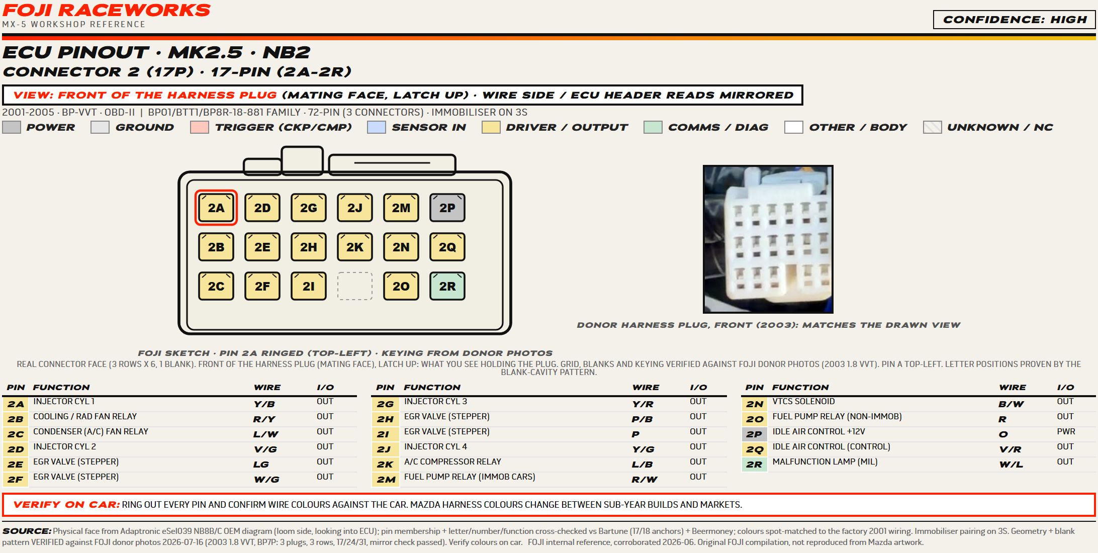
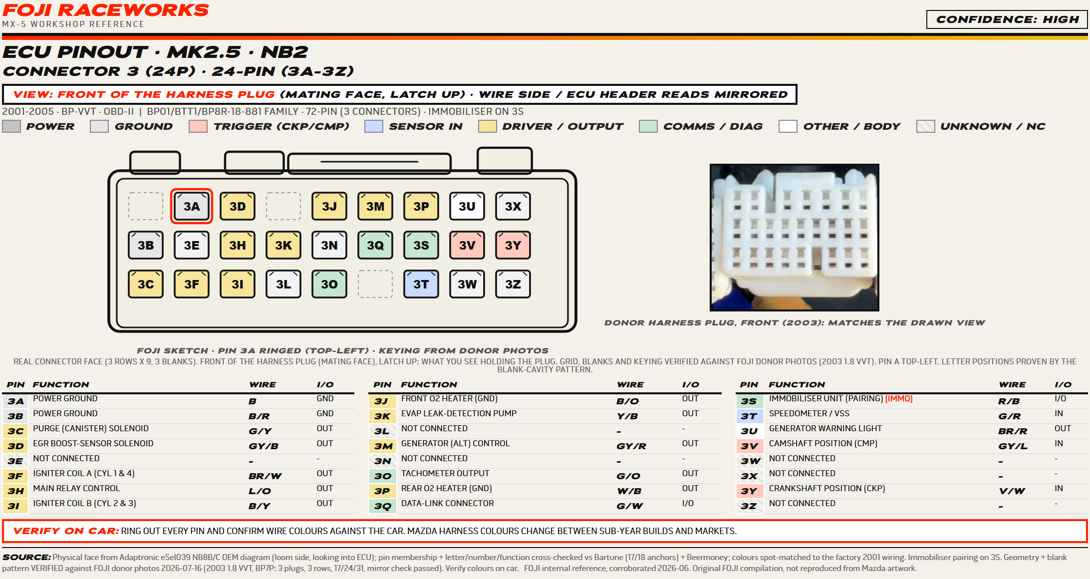
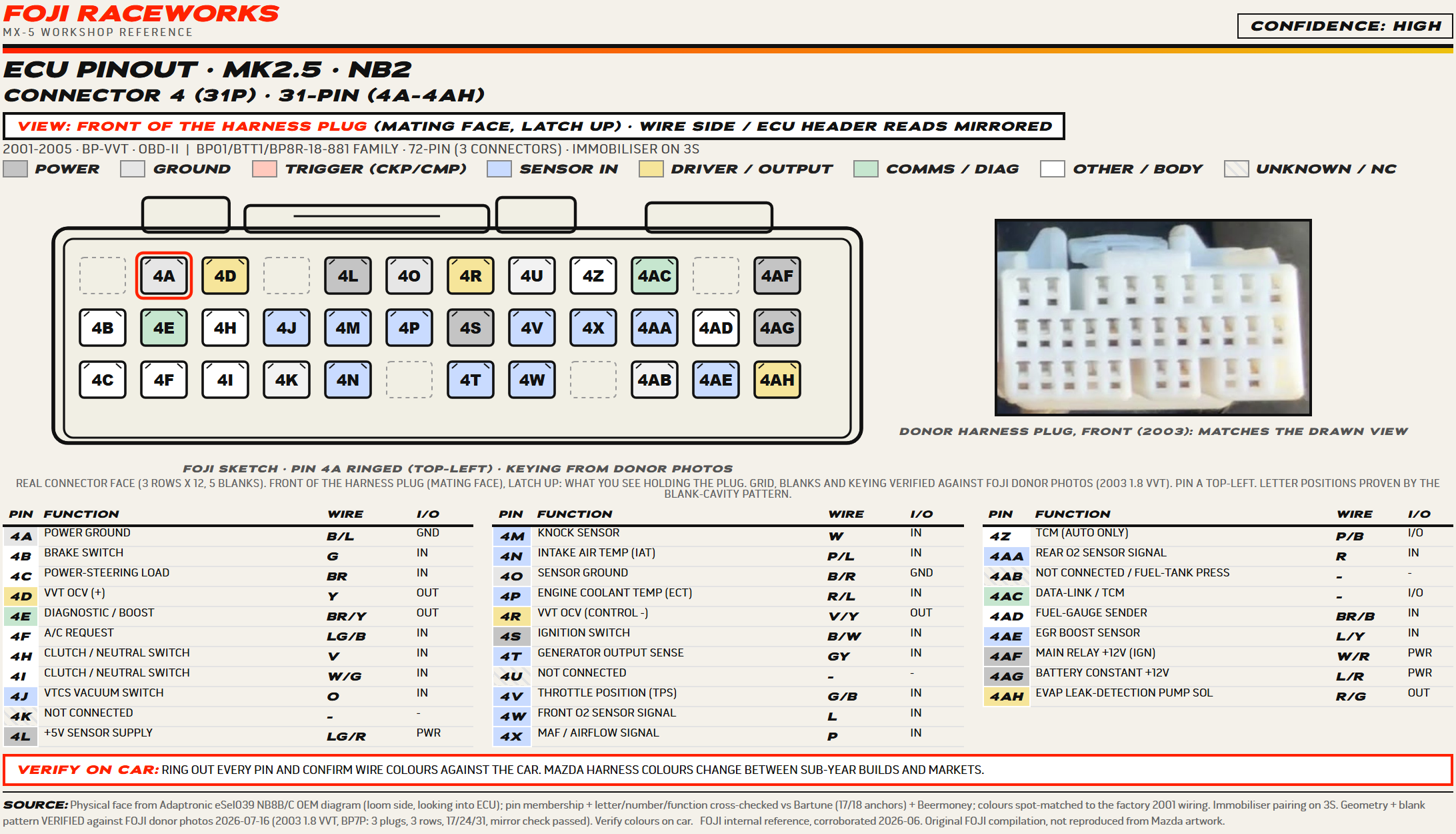
The strongest set of the four. The grid, the blank cavities and the mirror were all verified against a real donor plug from a 2003 1.8 VVT, and the colours were spot-checked against the factory 2001 wiring and matched. This is the VVT engine, so the oil control valve lands on pins 4D and 4R, and the ECU is married to the immobiliser on pin 3S.
Still to confirm on car
- The VVT oil control valve high and low sides (4D and 4R) and the immobiliser versus non-immobiliser fuel-pump split (2M and 2O) are worth confirming on your own car before you rely on them.
The NA8 (1996 to 1997) and the NC (2006 to 2015) are still to come.