
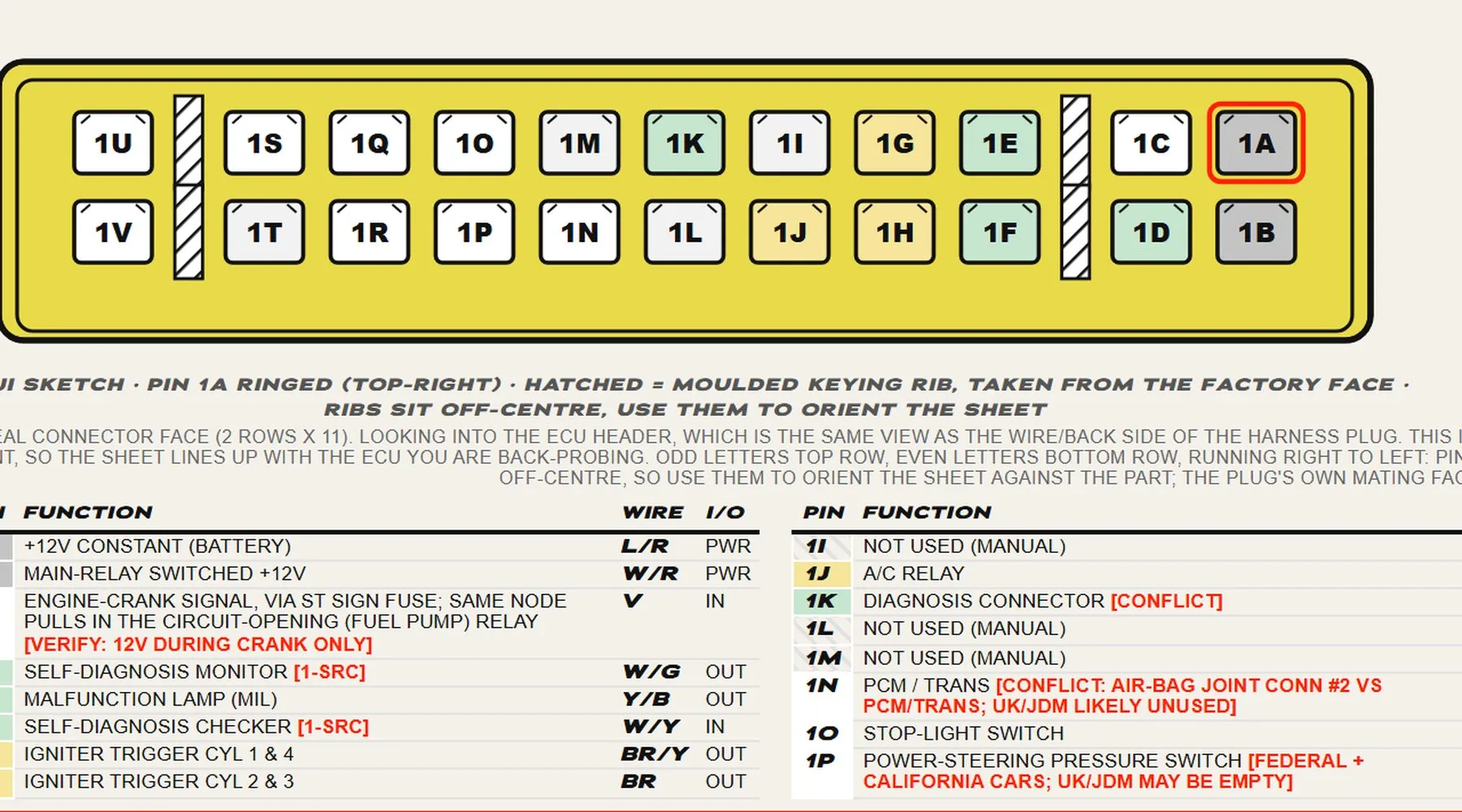
Three Mk1 NA sheets: the 1989 to 1993 1.6, the 1994 to 1995 1.6 and 1.8, and the 1996 to 1997 NA8, which went OBD-II on three plugs. The two OBD-I faces come off donor plugs and ECUs on the bench, the NA8 face is drawn on the NB1 face, and the colours are read from the factory US diagrams. Confidence is high on the 1994 to 1995 sheet and medium on the other two. The full how to read a sheet is on the ECU pinouts hub.
Read this first
Wire colours change between year builds and markets, and the Mk1 colour tables are read from the factory US diagrams, so treat a colour as a starting point and the cavity map and function as the reference. Ring every pin out on your own car before you cut or crimp.
The Mk1 NA sheets
Tap a sheet for full size. Each has its own PDF for the bench.
Mk1 · NA 1.6
1989 to 1993
B6ZE, OBD-I, optical cam angle sensor, no immobiliser. Two connectors.
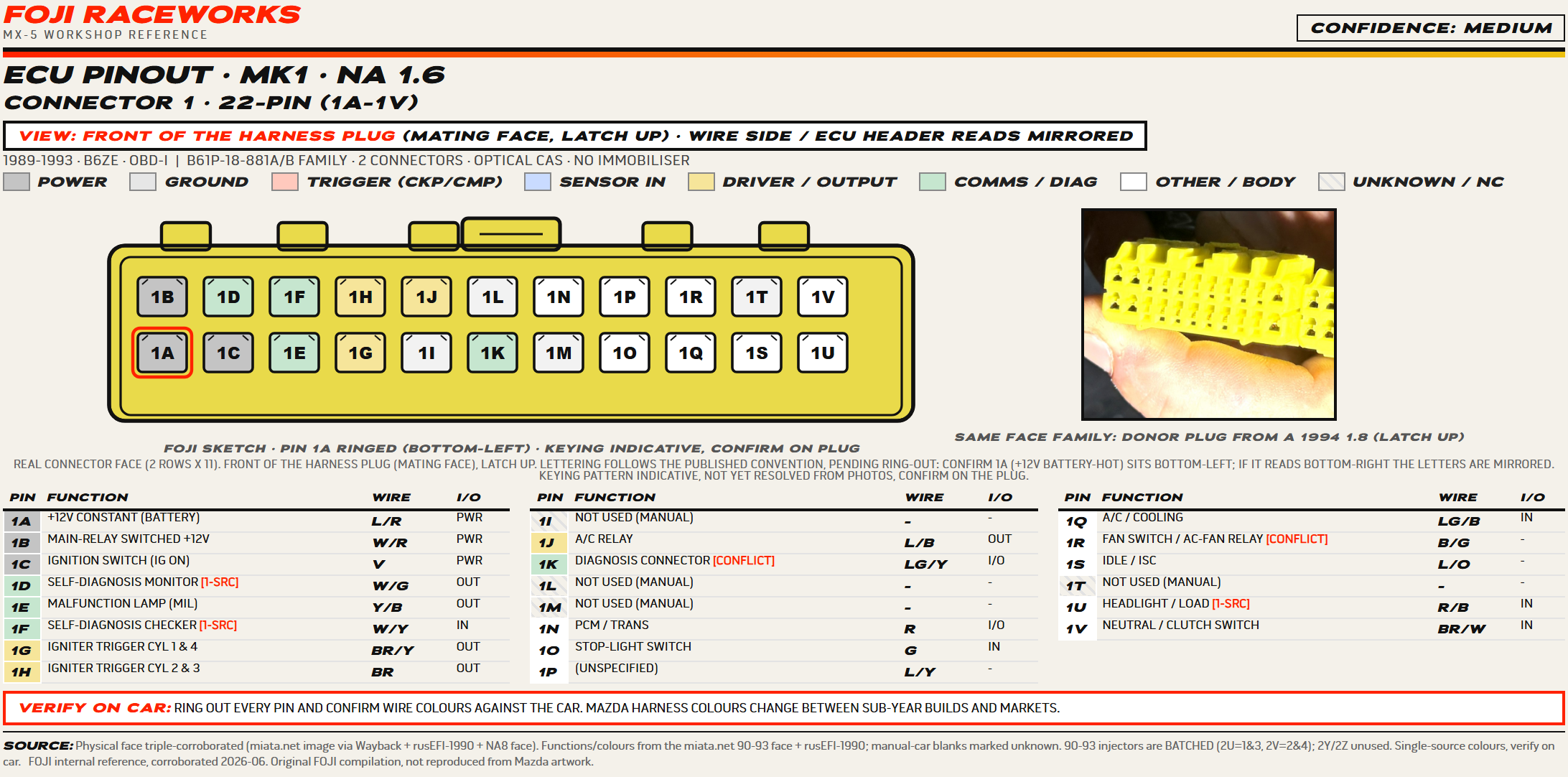
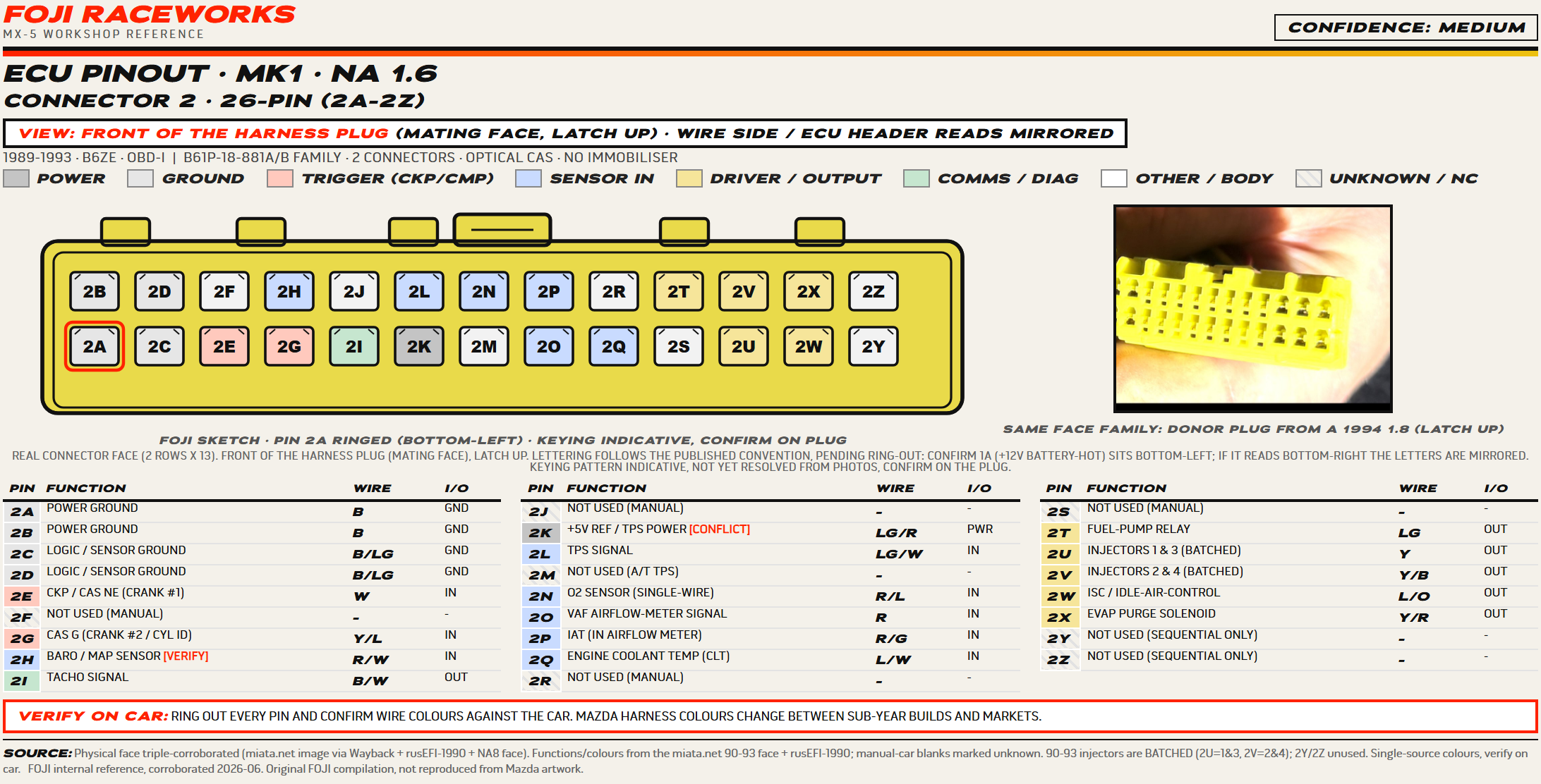
The early 1.6 ECU, two plugs, batched injectors on 2U for cylinders 1 and 3 and 2V for 2 and 4. The connector 2 cavities marked unused are the manual-car positions, so an automatic can carry a wire on some of them.
Still to confirm on car
- 1C and 2T disagree with the Motorsport Electronics 89 to 95 table, which reads 1C as the fuel pump output where we have ignition-switched 12V and puts the pump relay on 2T only from 1993 on, fitting the factory 89 to 92 face that shows 2T empty. Ring the pump feed out.
Mk1 · NA 1.6 & 1.8
1994 to 1995
B6 and BP, OBD-I, magnetic cam angle sensor. Two connectors.
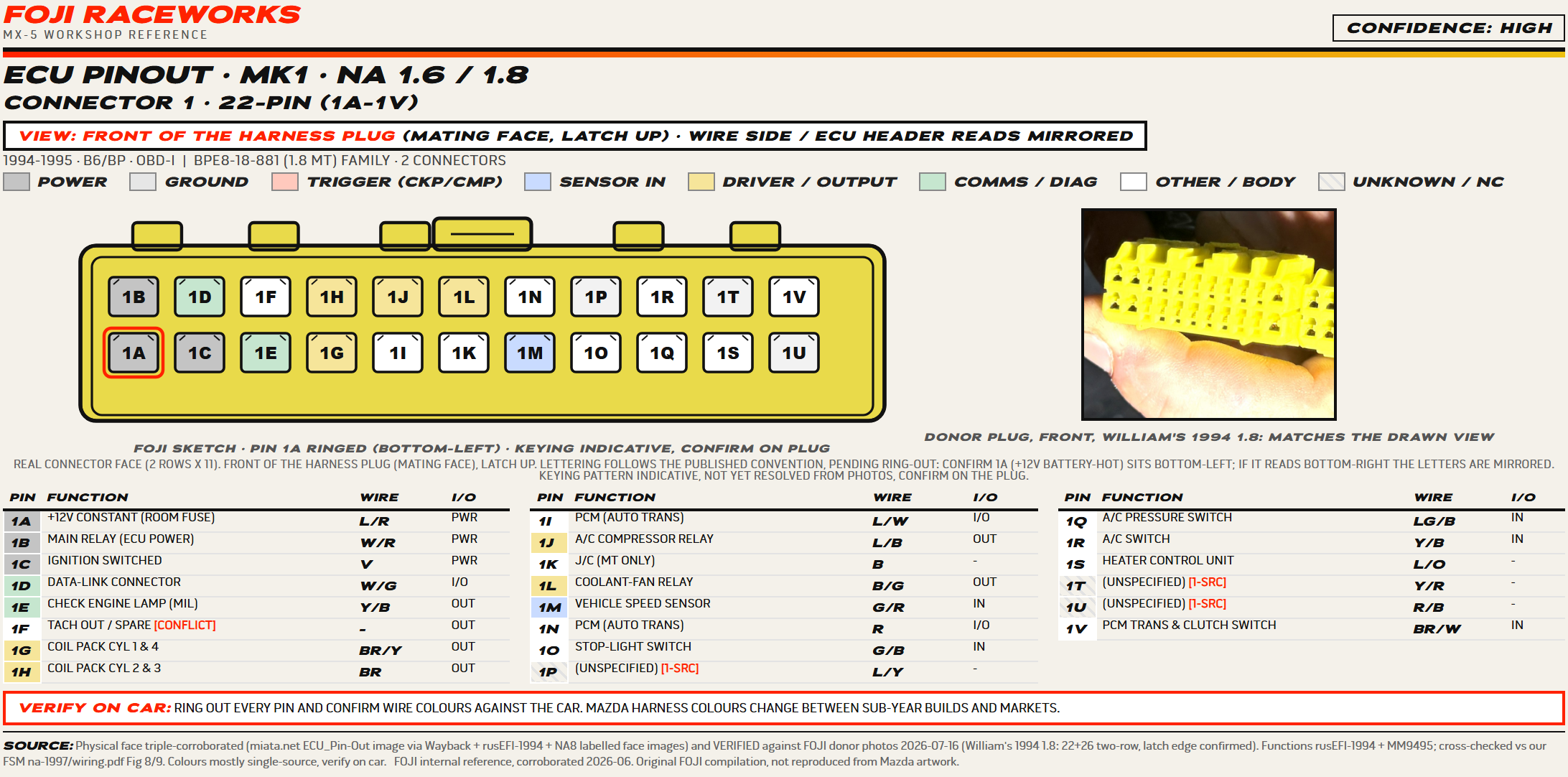
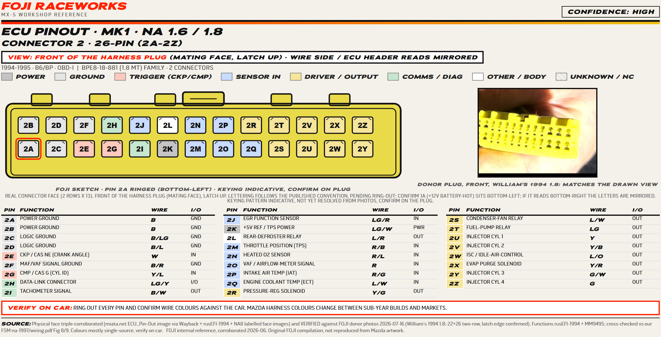
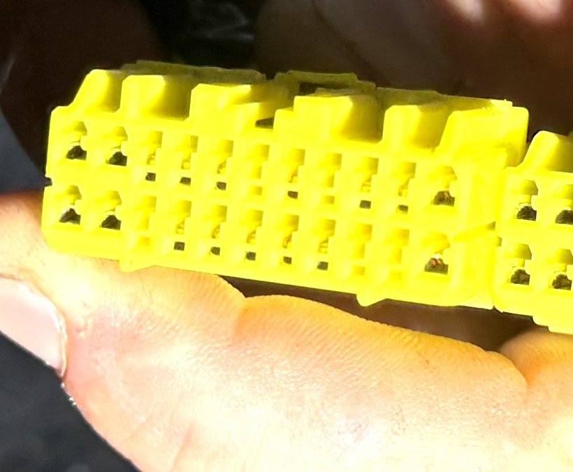
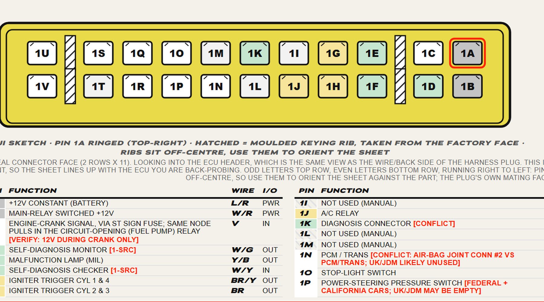
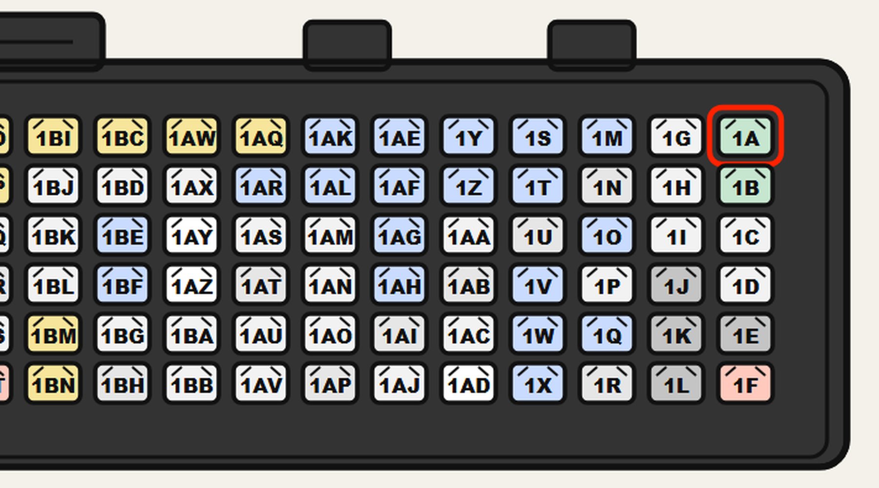
The plug the cavity map was checked against.
The cavity map is verified against a real donor plug from William’s 1994 1.8, and the two hatched keying ribs are moulded off-centre, so orient the sheet by them. Injection is sequential, one driver per cylinder, unlike the batched early 1.6. Colours are mostly single-source, so confirm them on the car.
Download this sheet (PDF, A4)Mk1 · NA8 1.8
1996 to 1997
BP, OBD-II, three connectors, 64 cavities, no immobiliser. The ECU sits below the right-hand seat. UK and JDM cars run the same three plug unit.
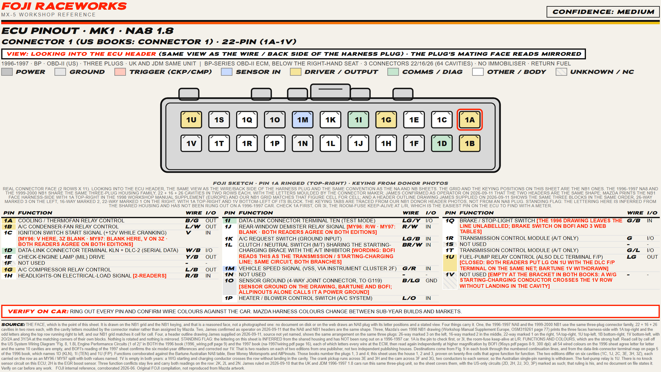
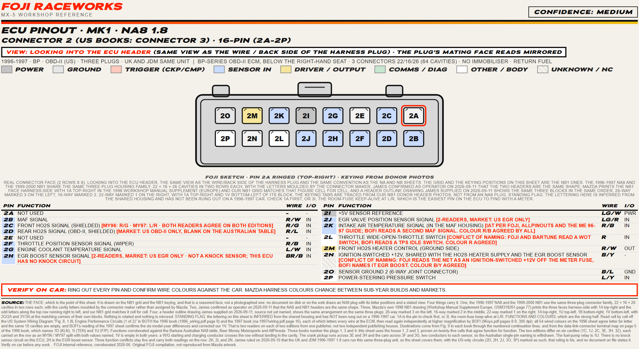
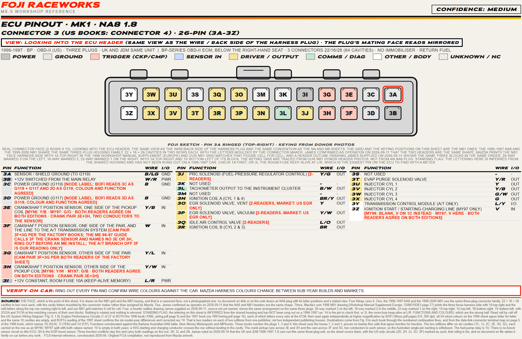
Functions and colours are read cell by cell off the factory US wiring diagrams for 1996 and 1997, then read again by a second reader, and all 54 wired colours on the 1996 sheet agree letter for letter, which is two readers on two editions from one publisher, not two publishers. Nobody publishes an NA8 plug face, so this one is drawn on the NB1 face on four grounds: the 1996 to 1997 and 1999 to 2000 cars share the 22 plus 16 plus 26 connector family, whose cavity letters are moulded by the connector maker and not chosen by Mazda, James confirms as operator that the two headers are the same shape, Mazda prints the NB1 face harness side in its own 1998 manual with 1A top-right and our NB1 drawing matches it cell for cell, and a header outline drawing, source not yet named, shows the same three blocks in the same order, 26 way left, 16 middle, 22 right, 1A in the same corner. So it is a reasoned face, not a photographed one, the sheet says so, and the American books number these plugs 1, 3 and 4 where we number them 1, 2 and 3 as the Australian table does, with both on each sheet.
Still to confirm on car
- The lettering is inferred from the shared housing, not rung out on a 1996 or 1997 car, so check 1A first, or 3I, the room fuse keep-alive at L/R, which is live with the key out.
- Three functions are argued over and the sheet carries both readings, 2K the intake air temperature sensor in the MAF housing or a second airflow signal, 2L a wide open throttle switch or an idle switch, 2N an ignition switched 12V supply or the EGR boost sensor, each with an agreed colour so a meter settles it.
- Six cavities change between the 1996 and 1997 cars and carry both values, 1C, 1J, 2C, 3E, 3H and 3Z, the start signal moving from 1C to 3Z and the demister off 1J. Check which year you are on.
How to read the sheets
- Drawn looking into the ECU header, the same view as the wire side of the harness plug.
- Pin A is ringed red, top-right on every sheet here, and the letters run right to left.
- Find a known pin first, the 12V feed or a ground, to fix left from right.
- The plug in your hand, mating face towards you, is the mirror of what is drawn.
- Each cavity is tinted by what the pin does:
By generation
 1989 to 1997This page
Mk1 · NA
Three sheets, the early 1.6, the 1994 to 1995 cars and the OBD-II NA8, confidence high on the 1994 to 1995 sheet and medium on the other two.
 1999 to 2005
Mk2 · NB
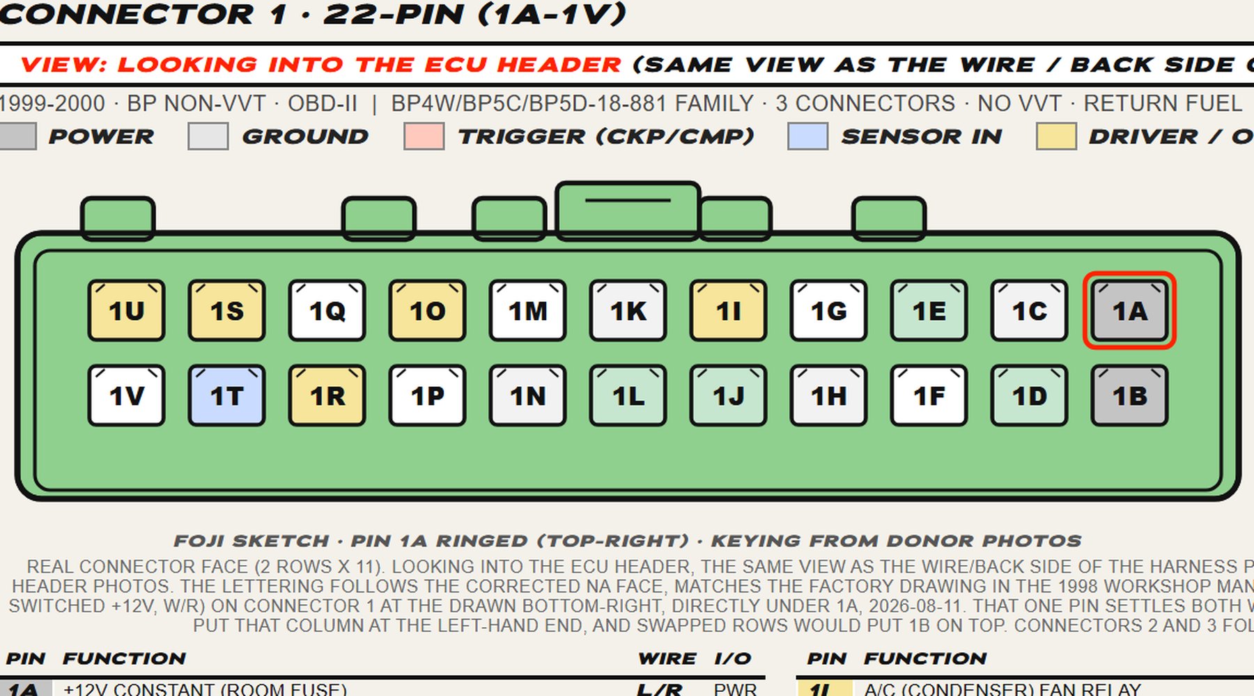
The NB1 and the NB2 VVT sheets, both OBD-II, three connectors each, confidence high on both.
 2006 to 2015
Mk3 · NC
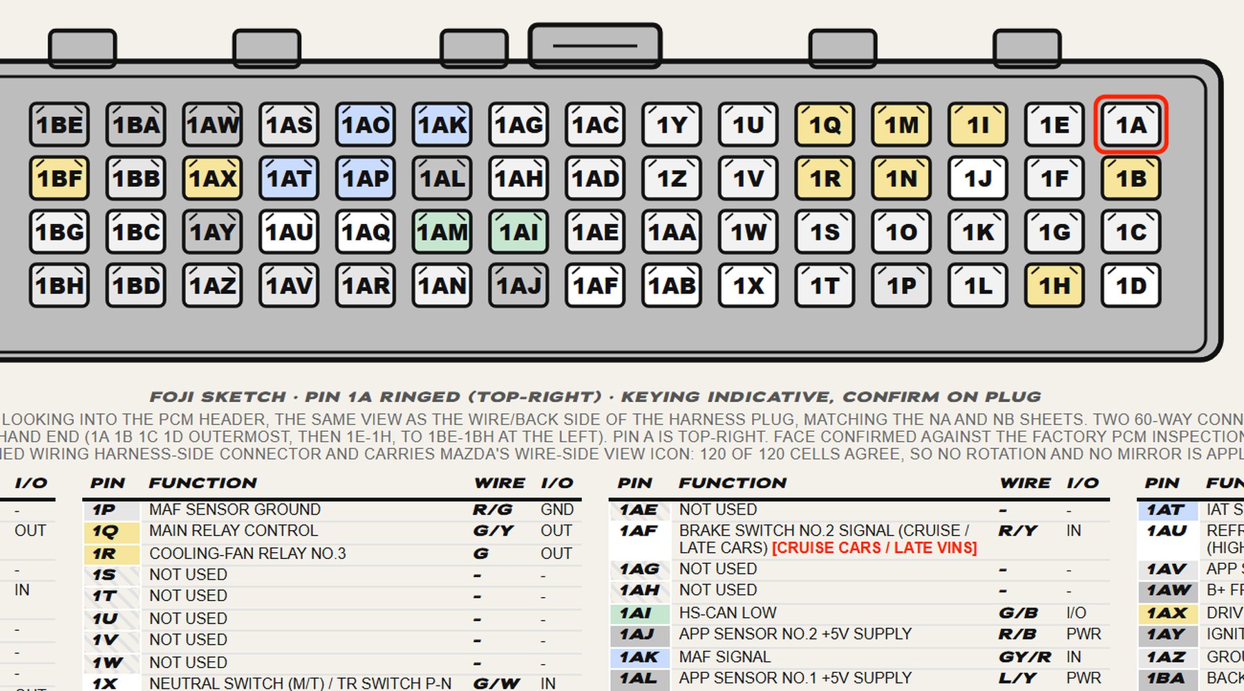
One sheet, drive-by-wire and CAN, two 60-way connectors and 120 terminals, confidence high.
 2015 on
Mk4 · ND
Two sheets, one per PCM, split by build number rather than by engine, confidence high on both.