
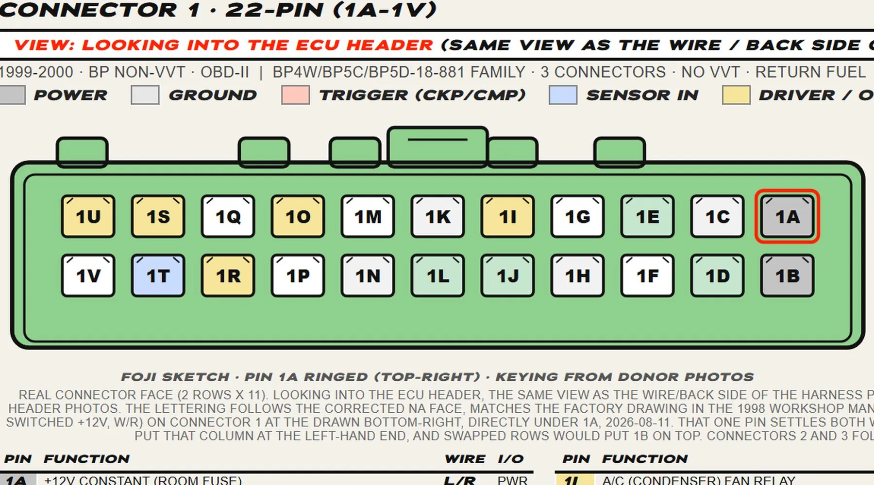
Two Mk2 sheets, the NB1 of 1999 to 2000 and the NB2 of 2001 to 2005. Both come off donor plugs and ECUs on the bench, and the colours are read from the UK factory wiring diagrams. Confidence is high on both. The full how to read a sheet is on the ECU pinouts hub.
Read this first
Wire colours change between year builds and markets, and the Mk2 and Mk2.5 colour tables are read from the UK factory wiring diagrams, so treat a colour as a starting point and the cavity map and function as the reference. Ring every pin out on your own car before you cut or crimp.
The Mk2 NB sheets
Tap a sheet for full size. Each has its own PDF for the bench.
Mk2 · NB1
1998 to 2000
BP non-VVT, OBD-II, return fuel. Three connectors, 64 positions.
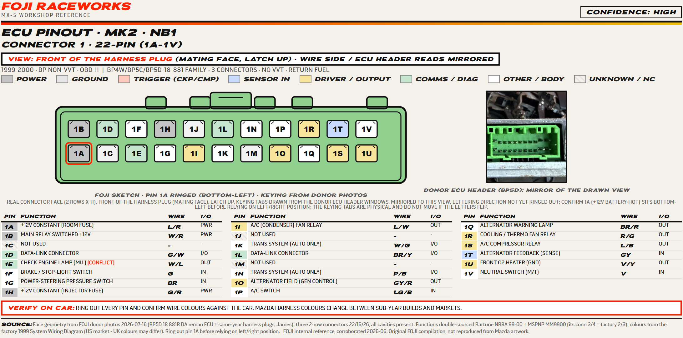
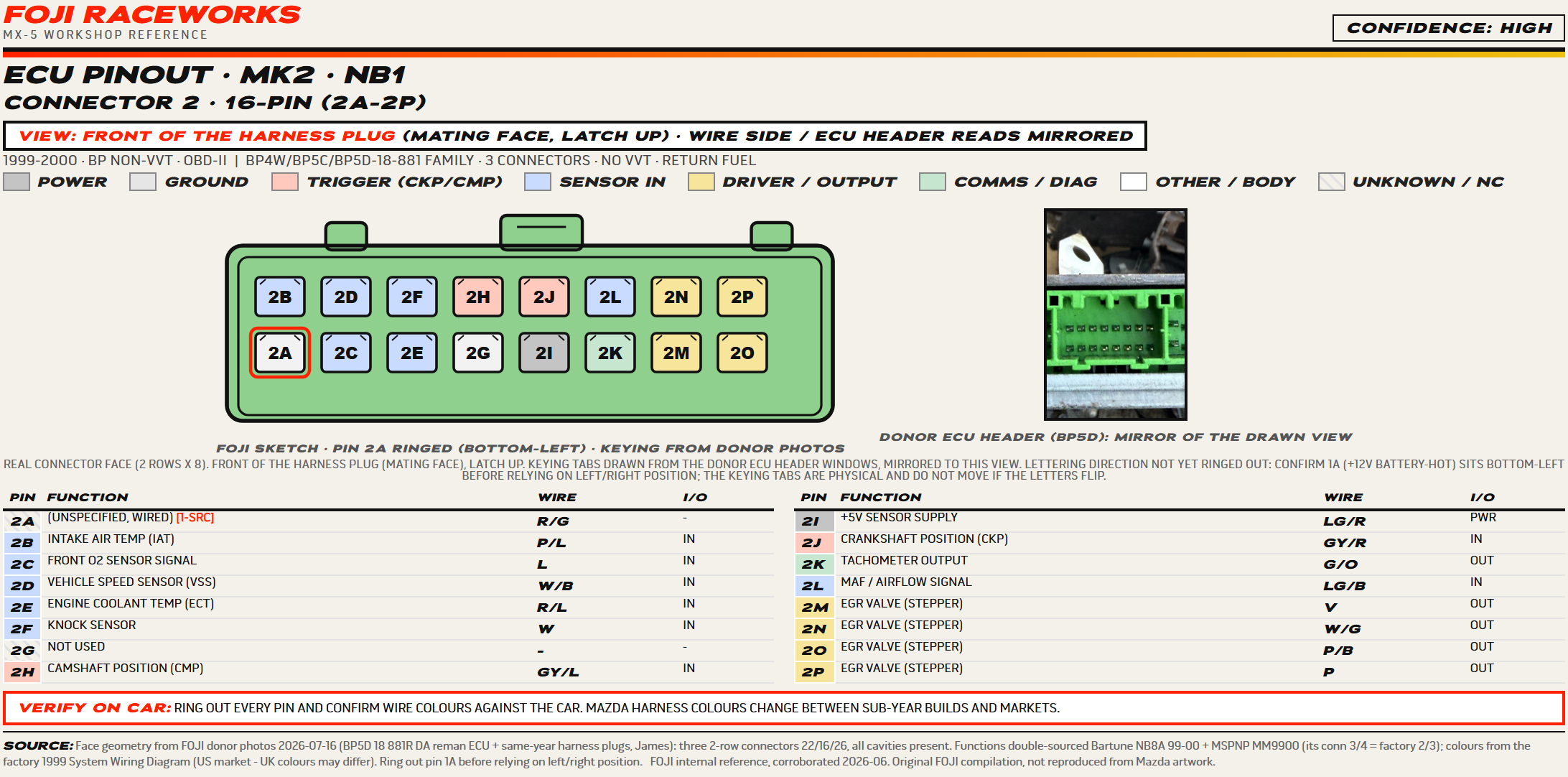
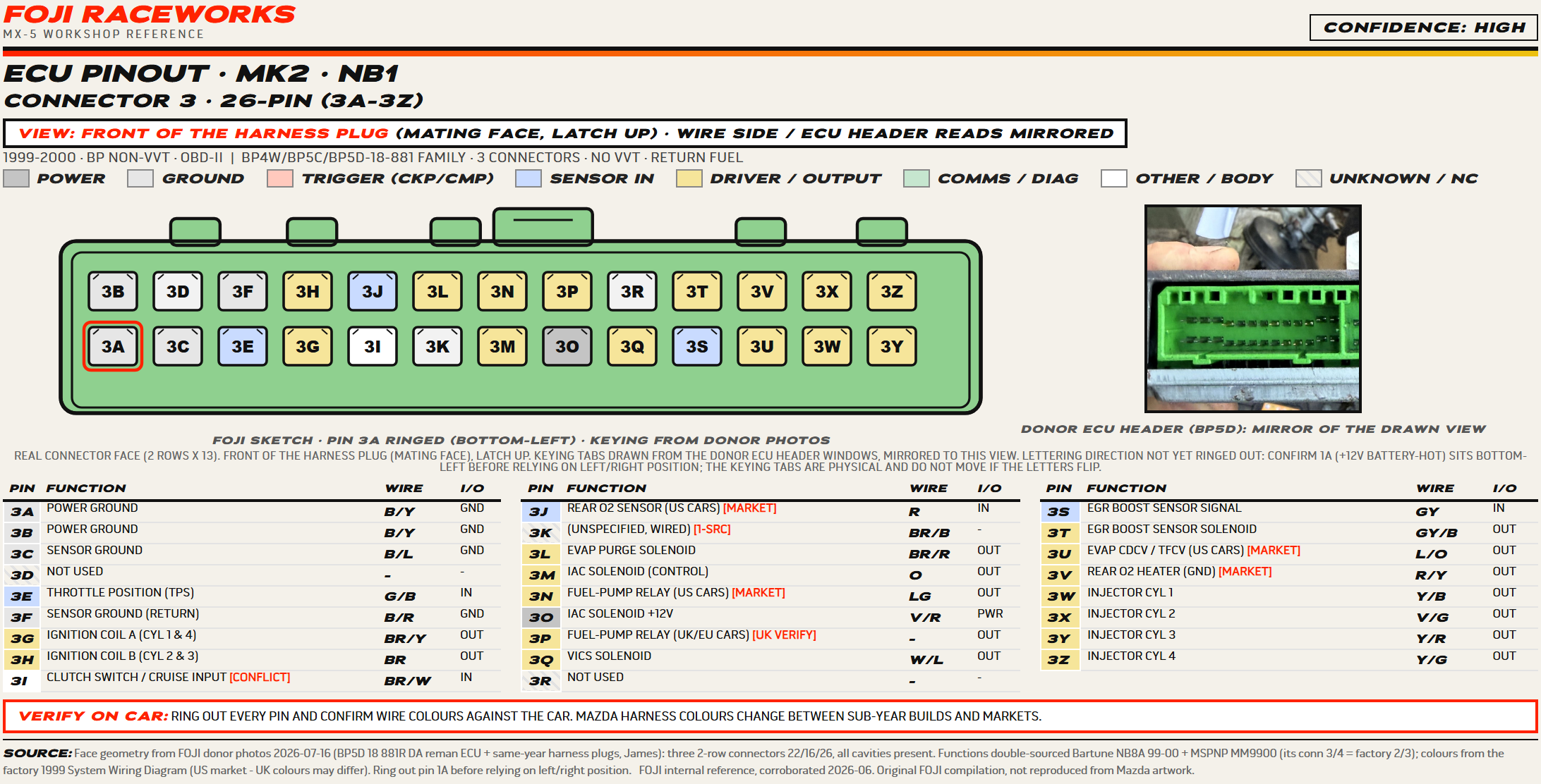
Drawn from our own donor parts, a BP5D reman ECU and same-year harness plugs from the scrapyard, then checked against the factory drawing in the 1998 workshop manual supplement, which prints the same three plugs harness side with 1A top-right. The lettering is confirmed on the part, pin 1B, the main relay switched 12V feed, reading at the drawn bottom-right directly under 1A, and the keying tabs sit as they do in our header photos. Every function is checked against the factory PCM terminal table and 60 of the 64 agree, and the colours are read cell by cell from the UK factory 1998 wiring diagram, so this is the UK car: immobiliser on 1J, fuel pump relay on 3P, US-only pins marked as blank cavities.
Still to confirm on car
- Pin 1H is the one open conflict: the factory PCM terminal table lists it unused, the factory wiring diagram draws a G/R wire on it, we read that wire off the 15A engine fuse and the US wiring names it a 12V constant off the injector fuse. Ring it out before you use the pin.
- Pin 1M, the transmission distinction pin that grounds on a manual car, is named by one source only and no wire colour has been captured for it.
- The US and UK looms differ on a handful of pins, and the sheet marks each one where they do.
Mk2.5 · NB2
2001 to 2005
BP-VVT, OBD-II, returnless fuel, immobiliser on pin 3S. Three connectors, 72 pins.
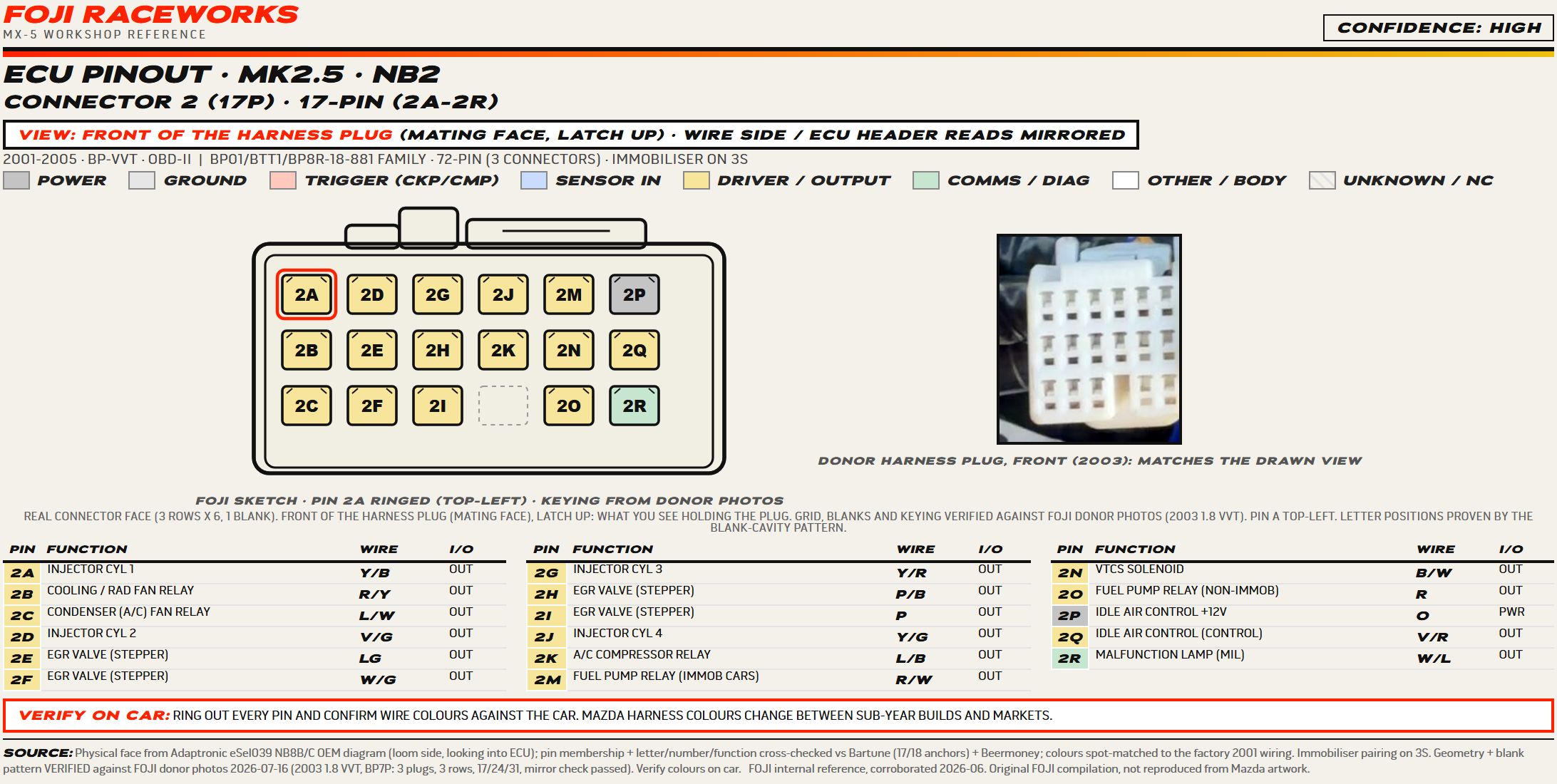
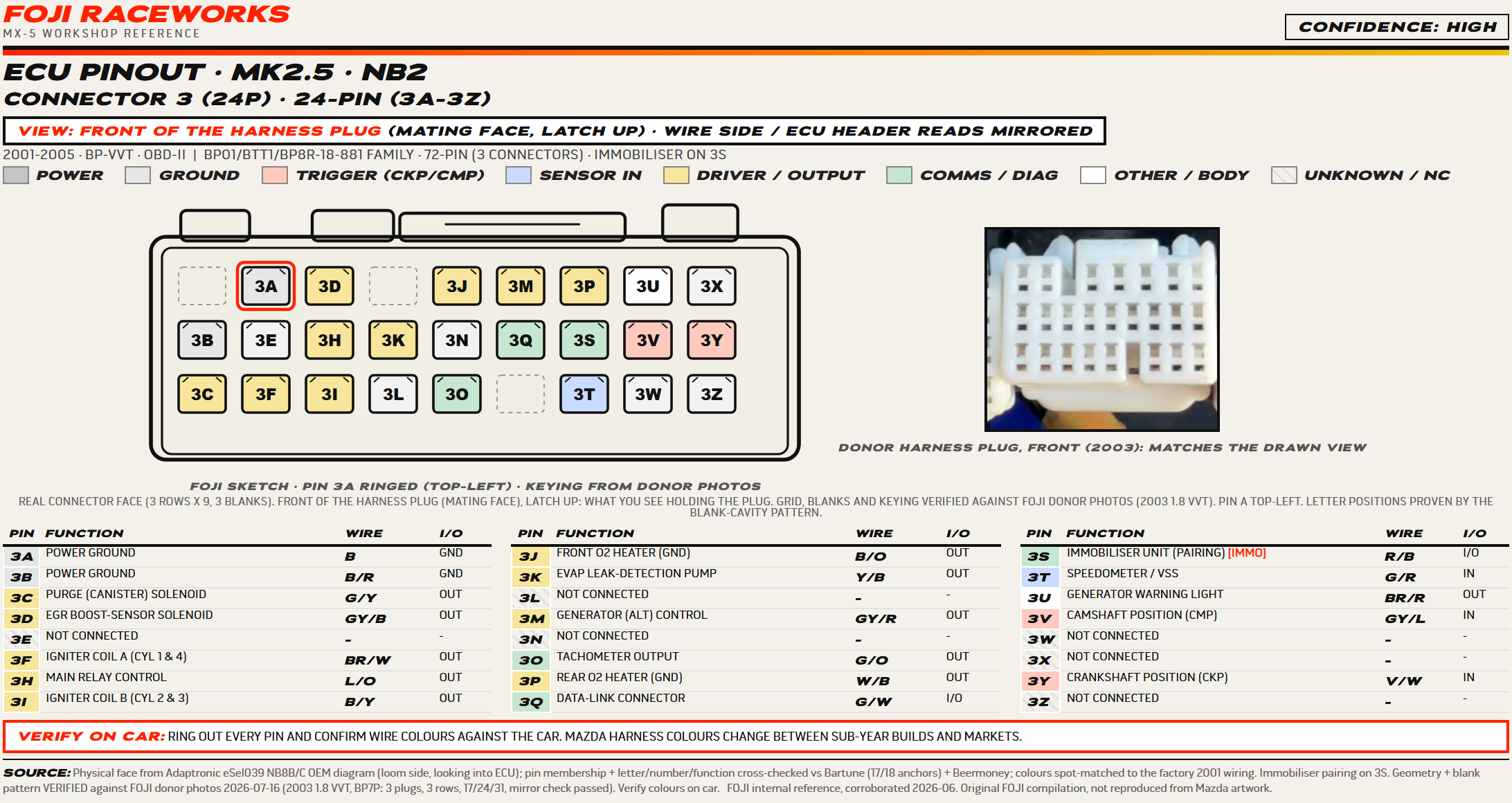
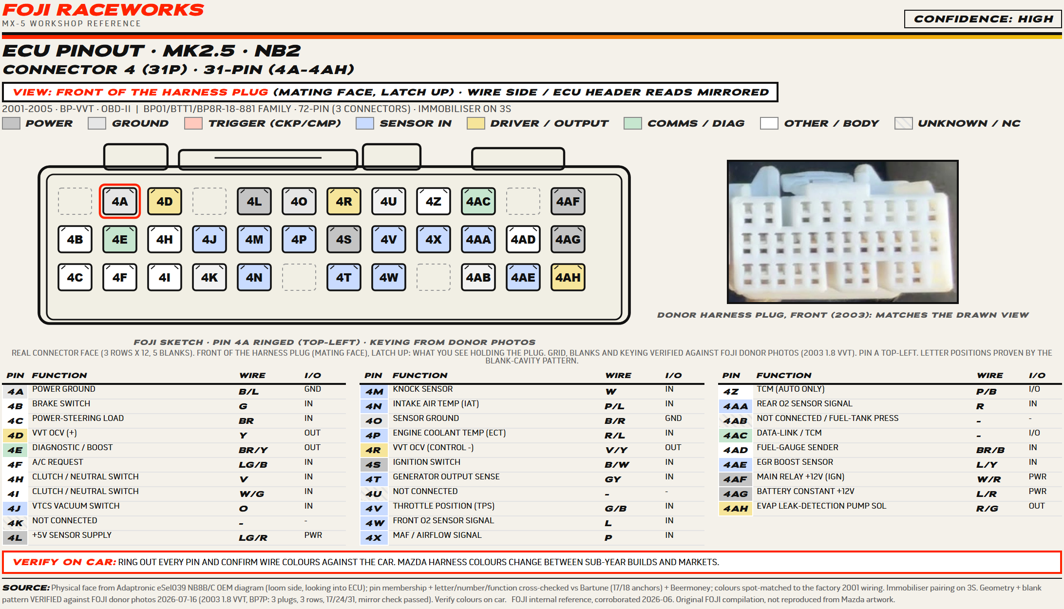
The strongest set of the Mk1 and Mk2 sheets: the grid and the blank cavities were verified against a real donor plug from a 2003 1.8 VVT, and every cell of the middle and bottom rows matches the factory 01-05 face. This is the VVT engine, so the oil control valve lands on 4D and 4R and the ECU is married to the immobiliser on 3S. Every function is checked against the factory PCM terminal table in the 2000 workshop manual supplement and 71 of the 72 agree, the colours against the UK factory 2001 and 2003 wiring diagrams, and seven US-only pins are vacant on European cars and marked so.
Still to confirm on car
- The VVT oil control valve high and low sides, 4D and 4R, and the immobiliser versus non-immobiliser fuel-pump split, 2M and 2O, are worth confirming on your own car.
- The UK main relay has no ECU control wire, so the 3H pin the Motorsport Electronics table lists is an empty cavity on a UK car. Ring it out before an ME install.
- The US and UK looms differ on a handful of pins, and the sheet marks each one where they do.
How to read the sheets
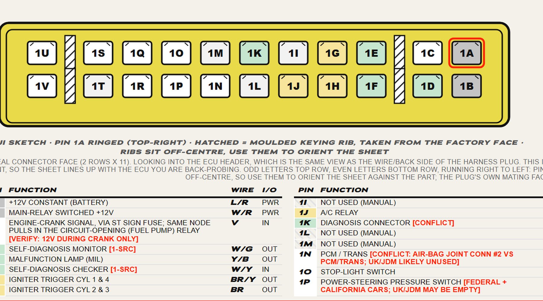
- Drawn looking into the ECU header, the same view as the wire side of the harness plug.
- Pin A is ringed red, top-right on every sheet here, and the letters run right to left.
- Find a known pin first, the 12V feed or a ground, to fix left from right.
- The plug in your hand, mating face towards you, is the mirror of what is drawn.
- Each cavity is tinted by what the pin does:
By generation
 1989 to 1997
Mk1 · NA
Three sheets, the early 1.6, the 1994 to 1995 cars and the OBD-II NA8, confidence high on the 1994 to 1995 sheet and medium on the other two.
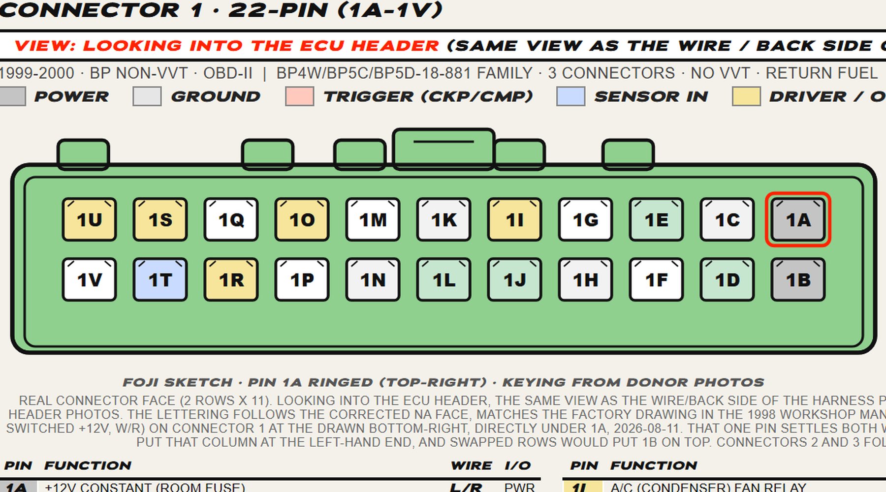 1999 to 2005This page
Mk2 · NB
The NB1 and the NB2 VVT sheets, both OBD-II, three connectors each, confidence high on both.
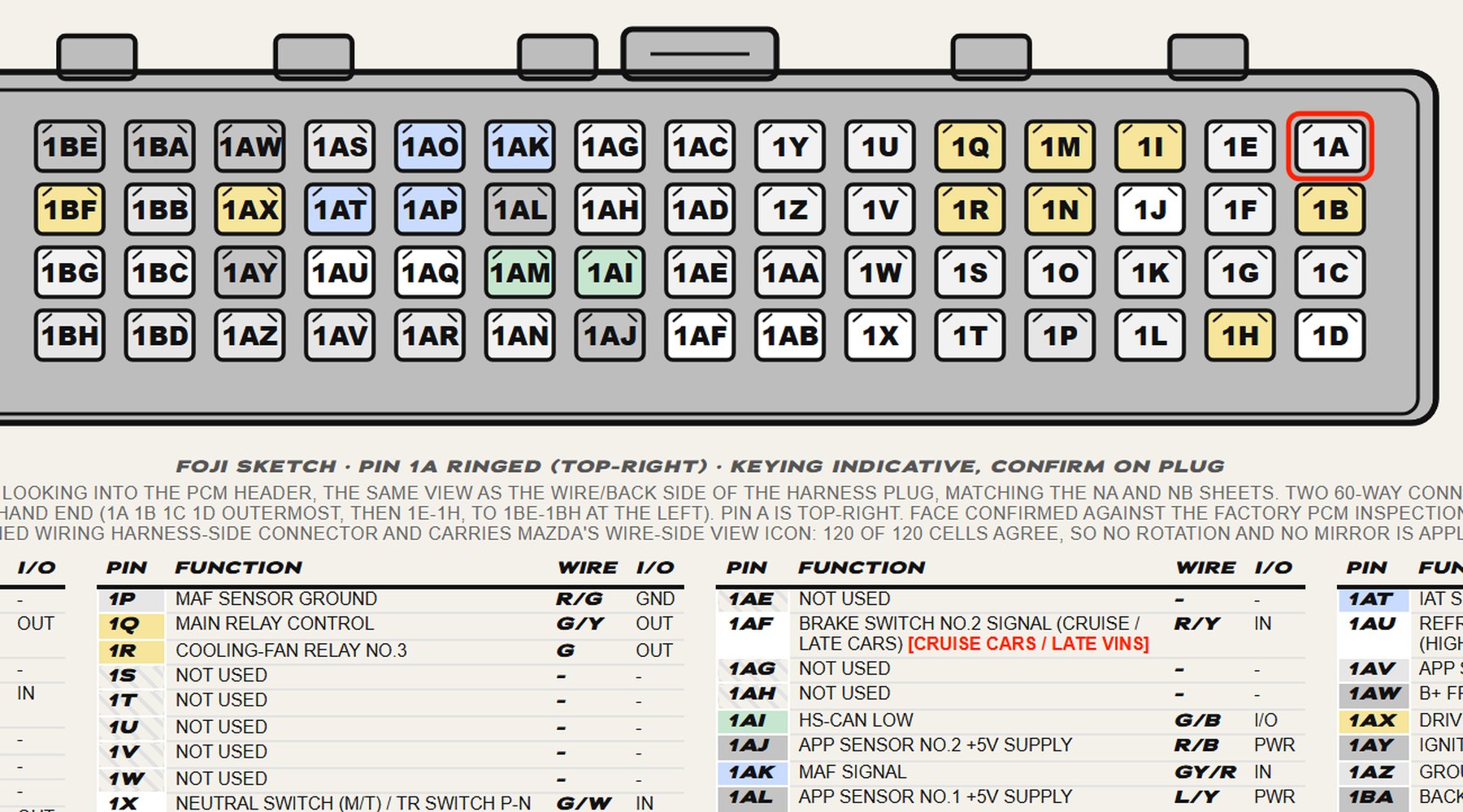 2006 to 2015
Mk3 · NC
One sheet, drive-by-wire and CAN, two 60-way connectors and 120 terminals, confidence high.
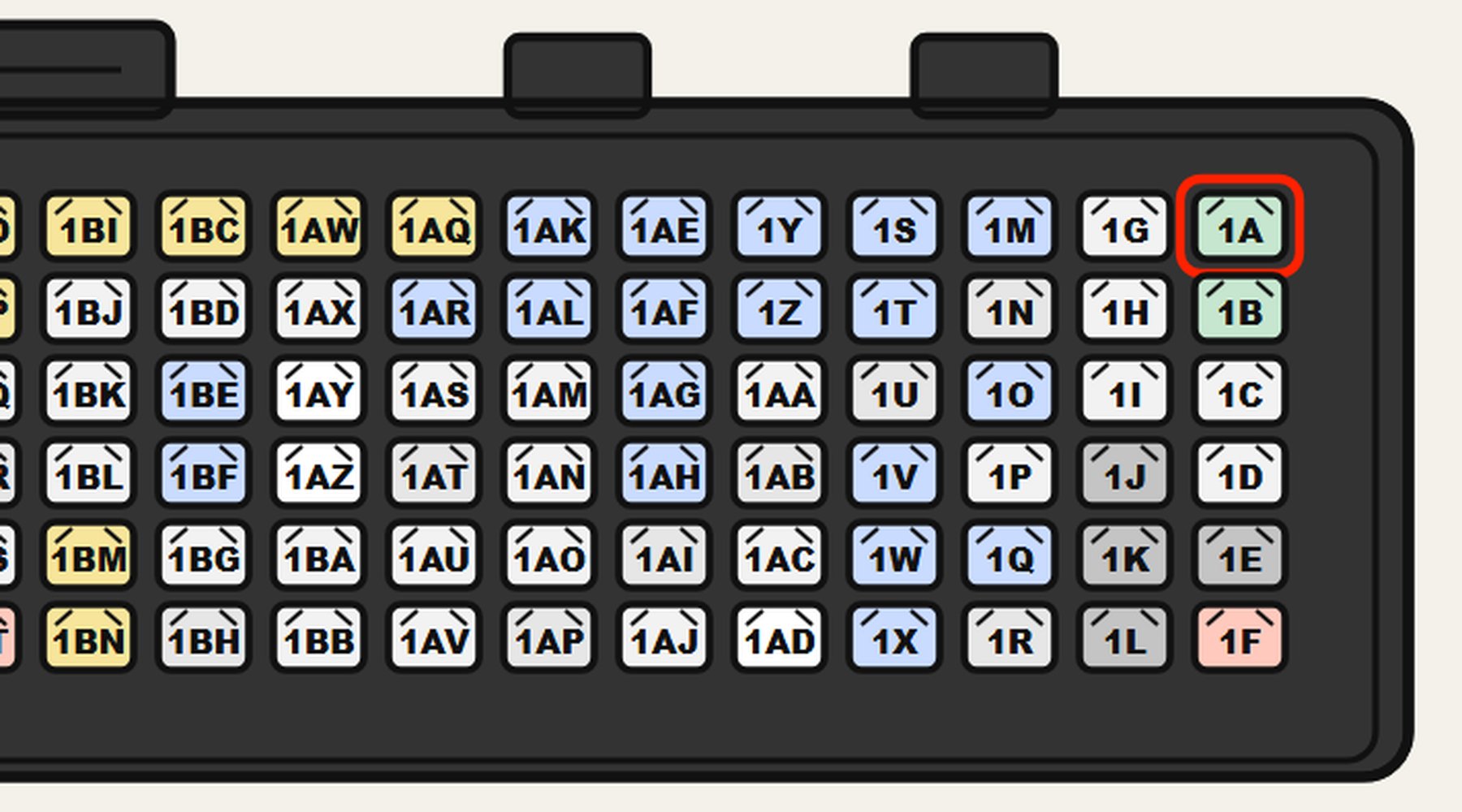 2015 on
Mk4 · ND
Two sheets, one per PCM, split by build number rather than by engine, confidence high on both.